Polaris 850 Axys
Installation Instructions Hot’n Shreddy Bag
The Hot’n Shreddy installation isn’t a difficult process but does require some disassembly and reassembly of your snowmobile. The instructions below have large photos and detailed process steps to guide your way. The most important thing is to take your time.
Dealer Installation Time: 1 Hour
The Hot’n Shreddy installation is also designed to be completed by a dealer in about an hour, so if you don’t want to take on the project then a dealer can support you with a minimal cost.
Step 1: Remove Plastics
Remove all plastics, this includes:
Left Side Panel
Right Side Panel
Hood
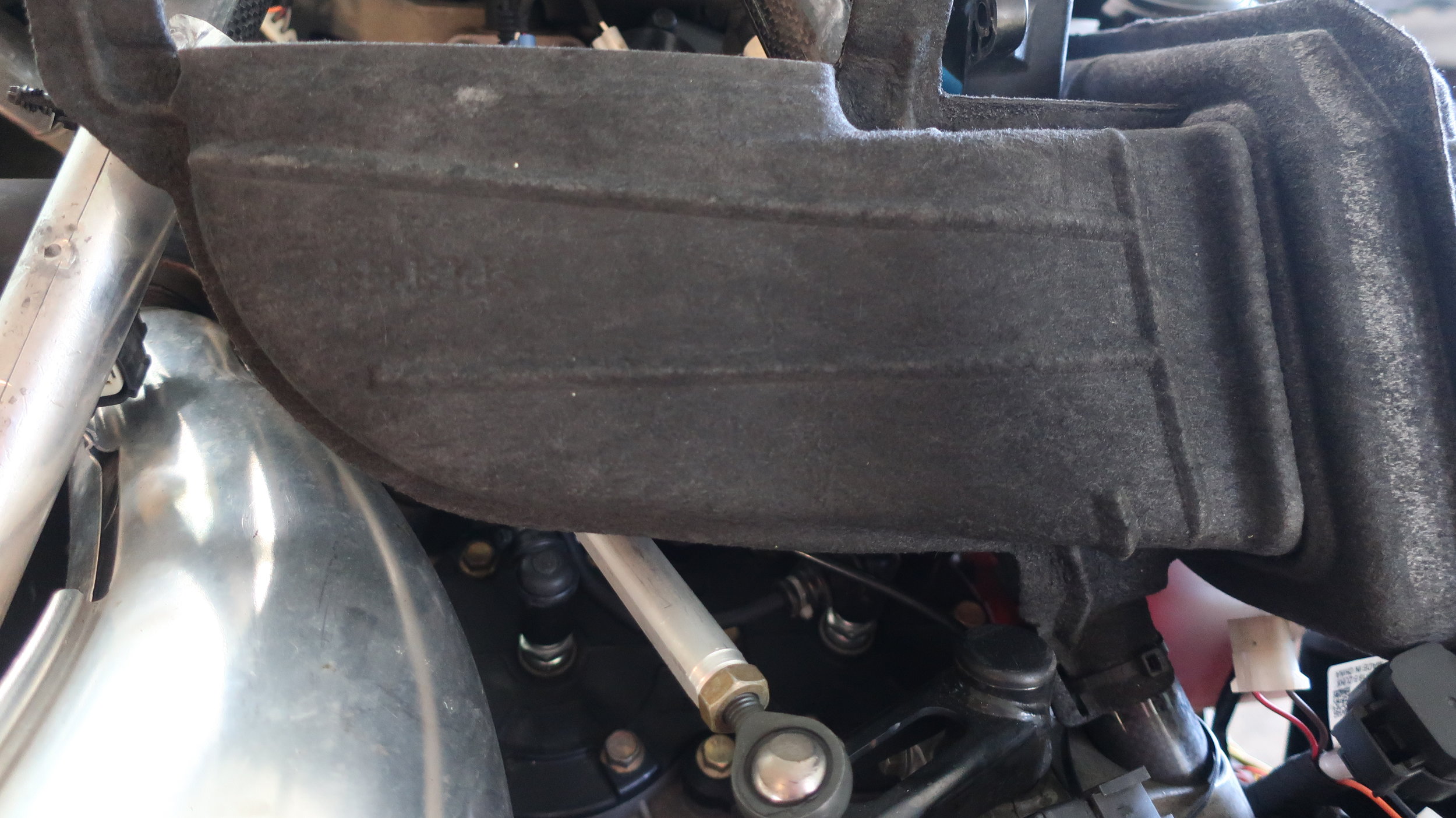
Step 2: Remove Air Box
Using a flat screw driver, remove air box by lifting plastic push pins. A needle nose pliers may be useful in the remove process as well.
Remove both torx screws located in front of the handlebar.
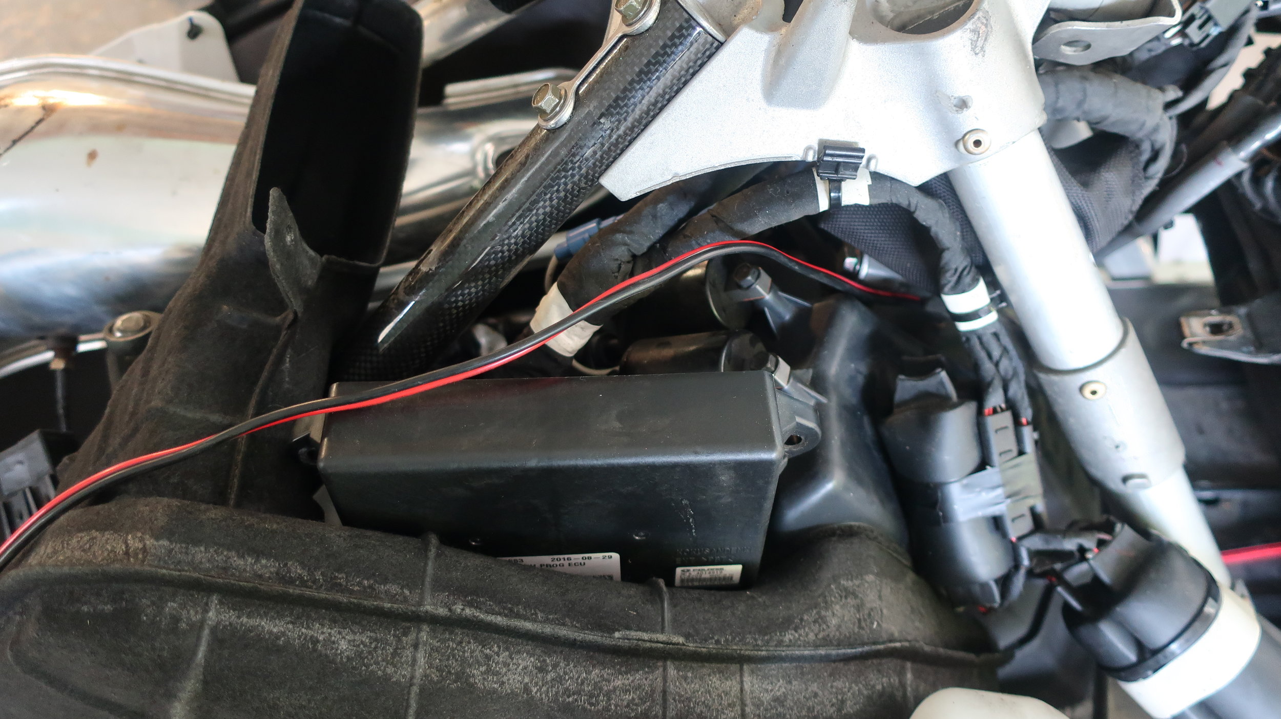
Using a 10 MM socket, remove hex bolts on the clutch side which attach the ECU. Let the ECU hang to the side.
Do not remove the air intake tube, you can leave this in place.
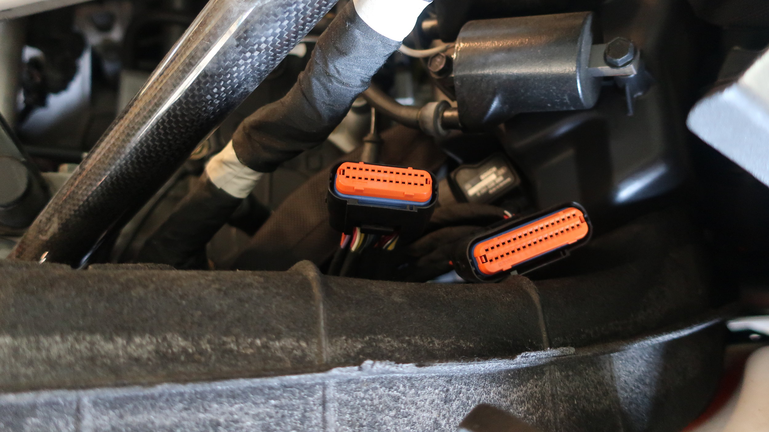
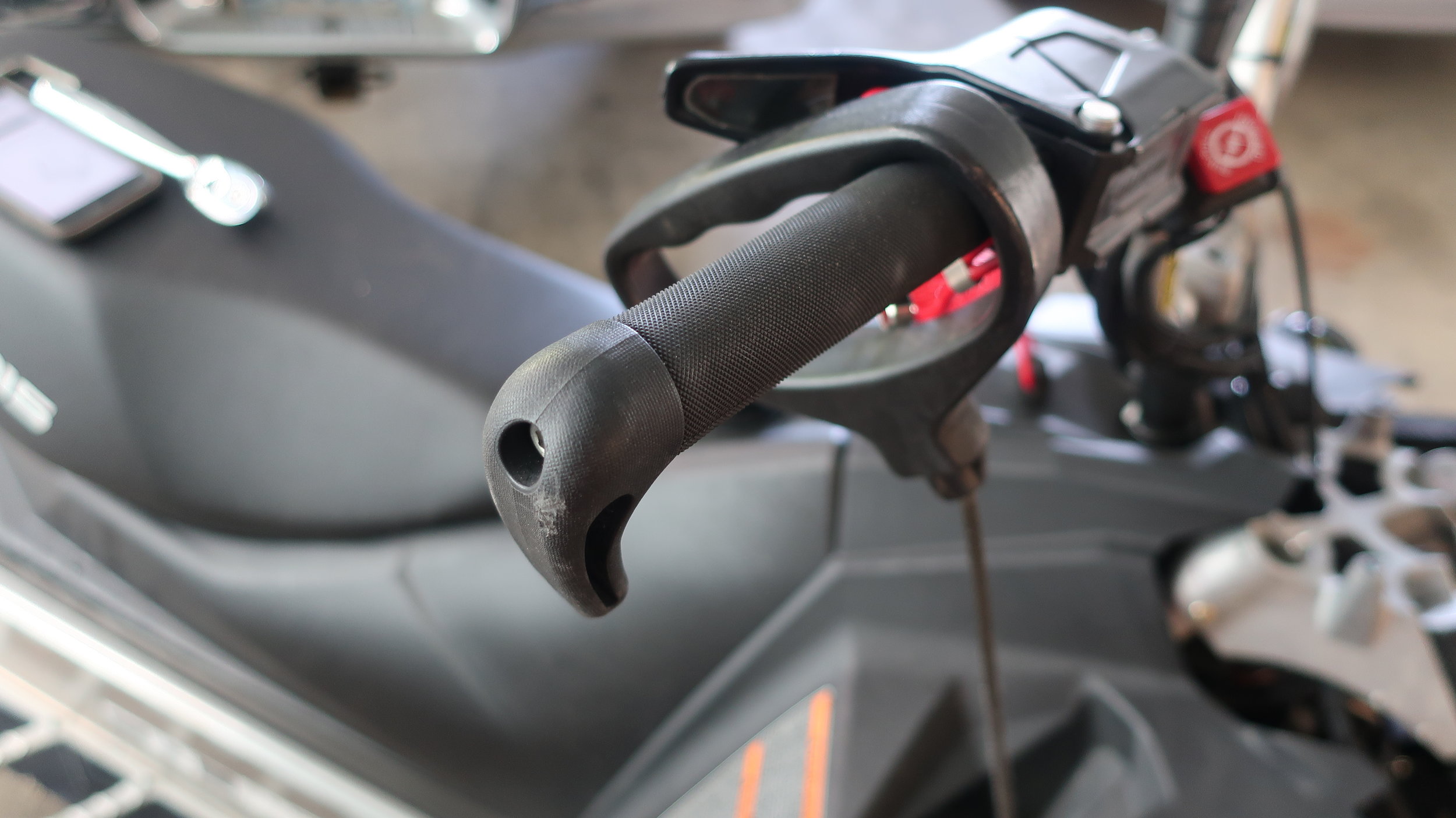
STEP 3: Remove Console
Using a flat screw driver, remove the console by lifting plastic push pins. A needle nose pliers may be useful in the remove process as well.
Gently extend pull start cord and hook onto throttle side handlebar
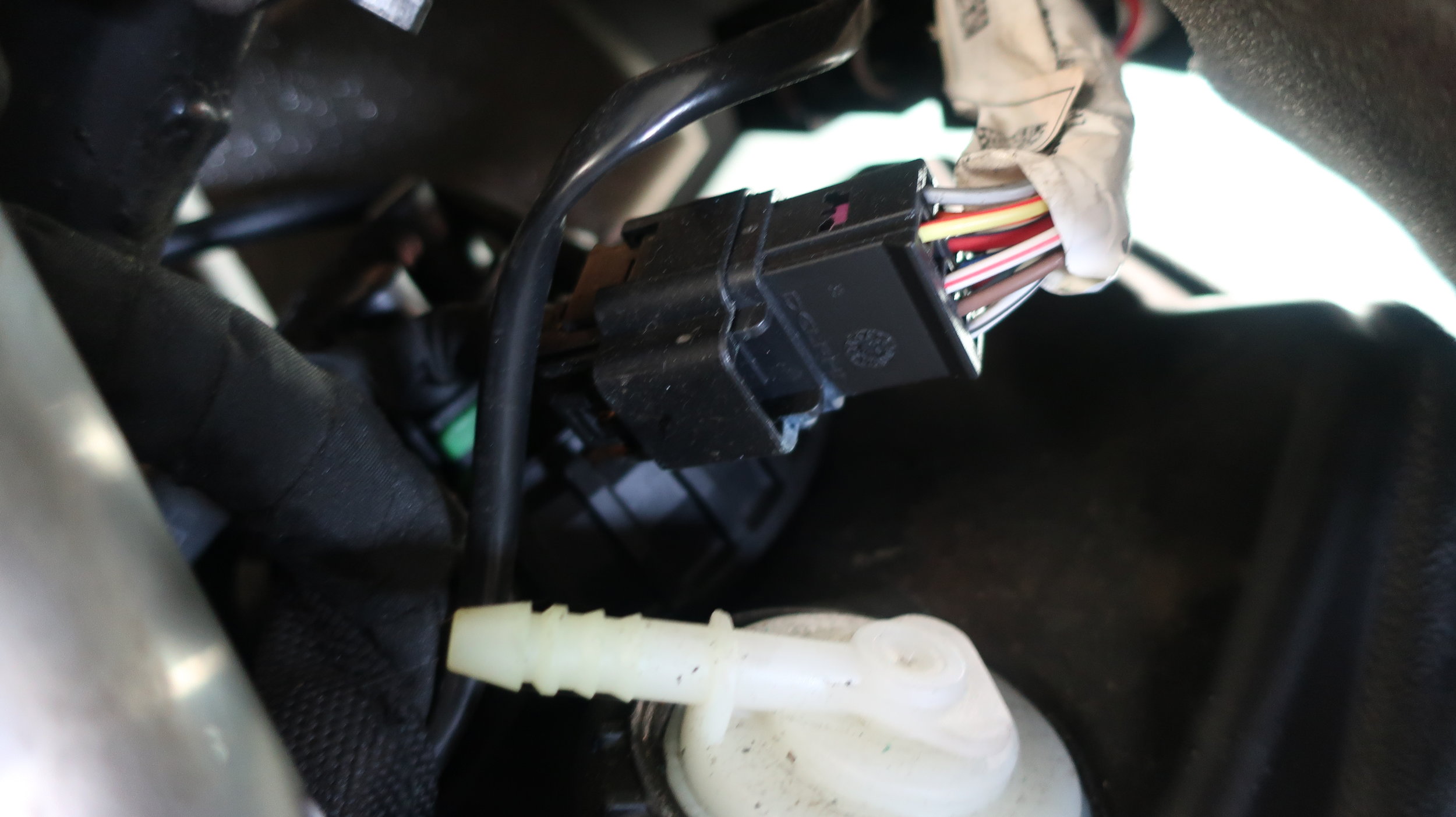
Remove connectors to light switch, heated grip and mode switching. There is a single wiring connector just in front of the gas tank under the console
Ease the console out of the way by moving it into hanging position on the exhaust/throttle side
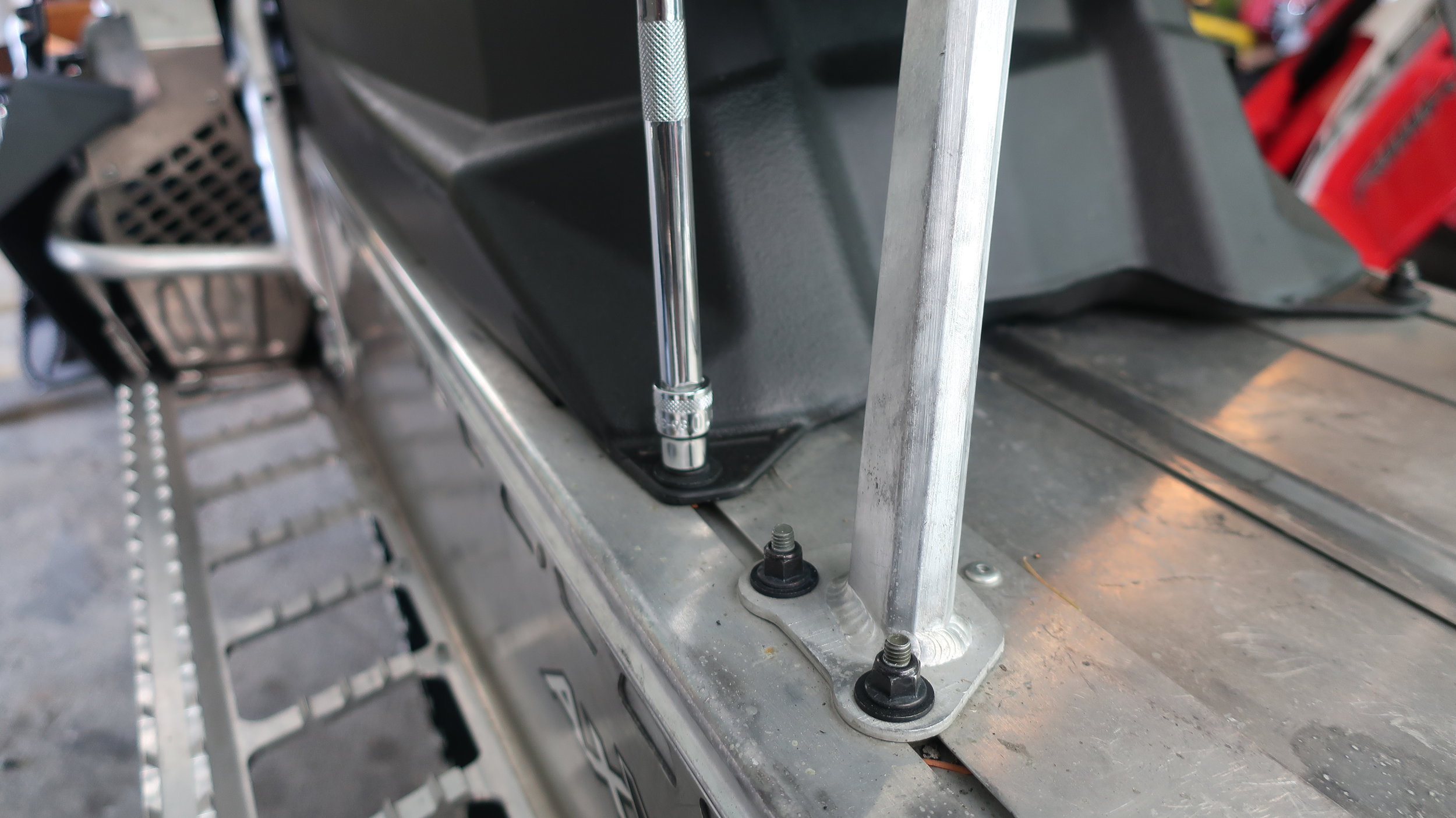
STEP 4: Remove SEat Completely and Loosen Rear of Gas Tank
With the same 10mm socket, remove the nuts holding the seat flange located at the rear of the seat on the tunnel
Using the same 10mm socket, remove the rear tank nuts at the back of the tank
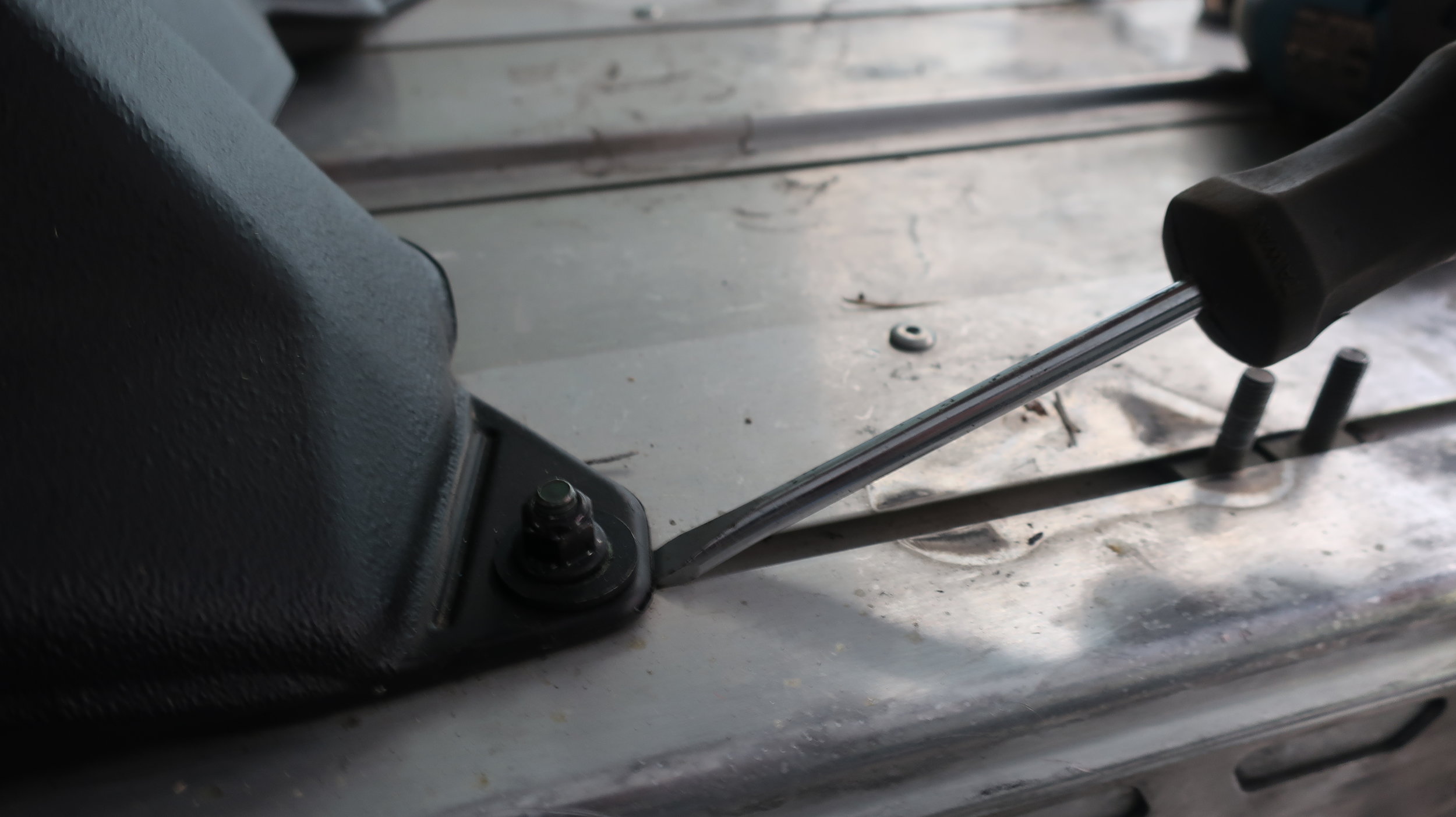
NOTE: If nuts are not loosening, this means the bolt is spinning which is common, locate a thin flat screw driver and GENTLY apply upward pressure to the back of the bolt through by sliding into the track.
DO NOT PRY WITH EXCESS FORCE OR JAM A LARGER SCREW DRIVE INTO THE TRACK CHANNEL
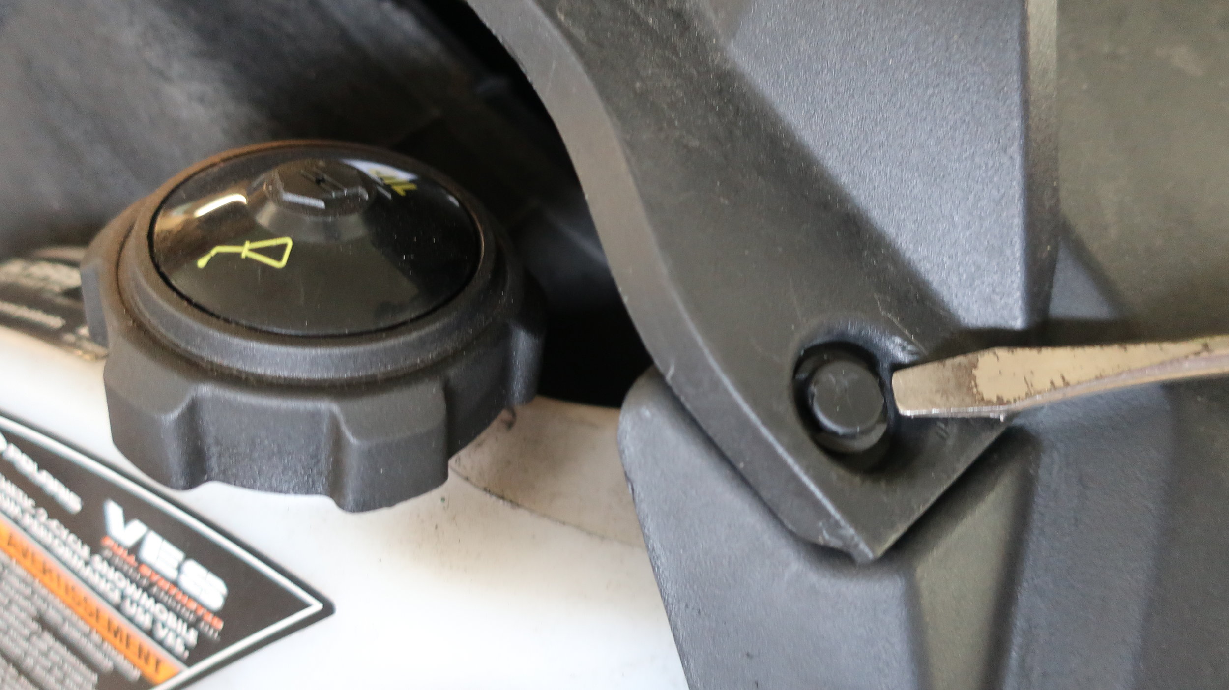
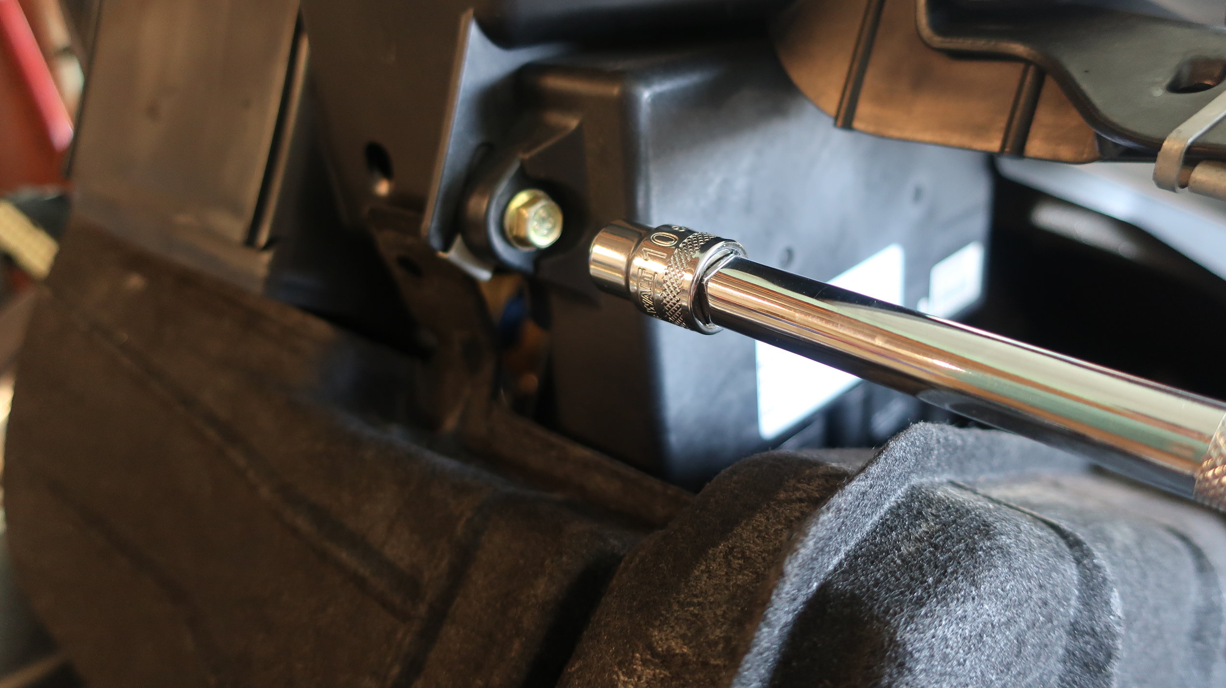
STEP 5: Remove Tank Bolt from Front of Gas Tank
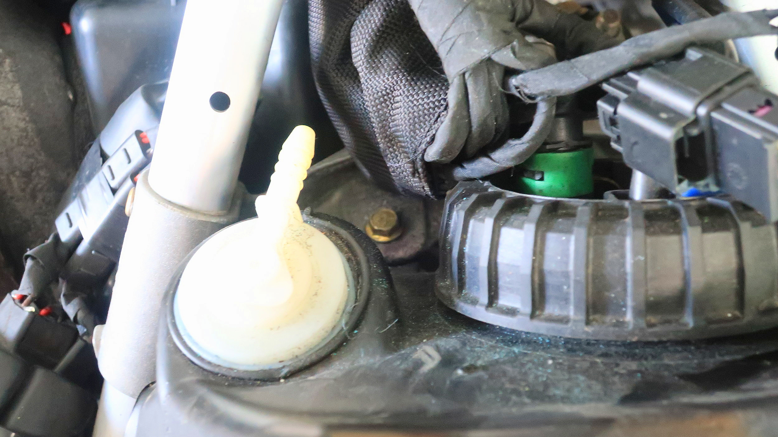
Using a 10 mm socket and extension, remove the tank bolt located in the front of the gas tank close right by the white breather. Moving your handlebars to the right will provide a little more working space
STEP 6: SLide tank backwards and Run Tank Wire
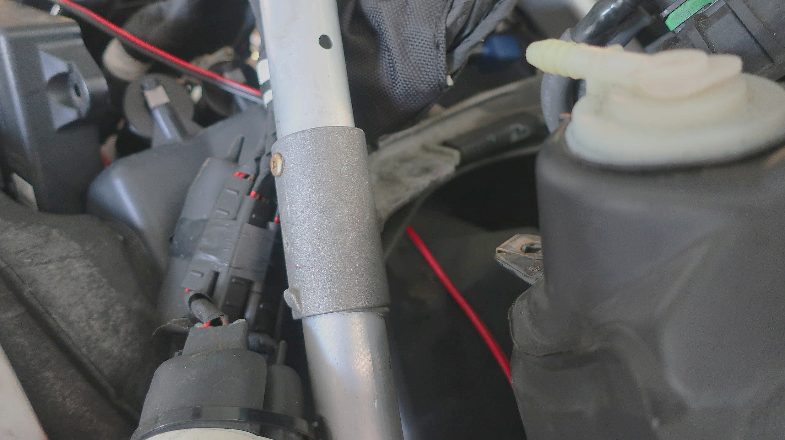
Slide gas tank backwards, if the tank does not slide easily the tank is likely stuck to the foam. Lift gently from the rear of the tank to free off the foam and then slide. The fuel lines are still attached so don’t slide to fast and pay close attention to the tension on the fuel lines.
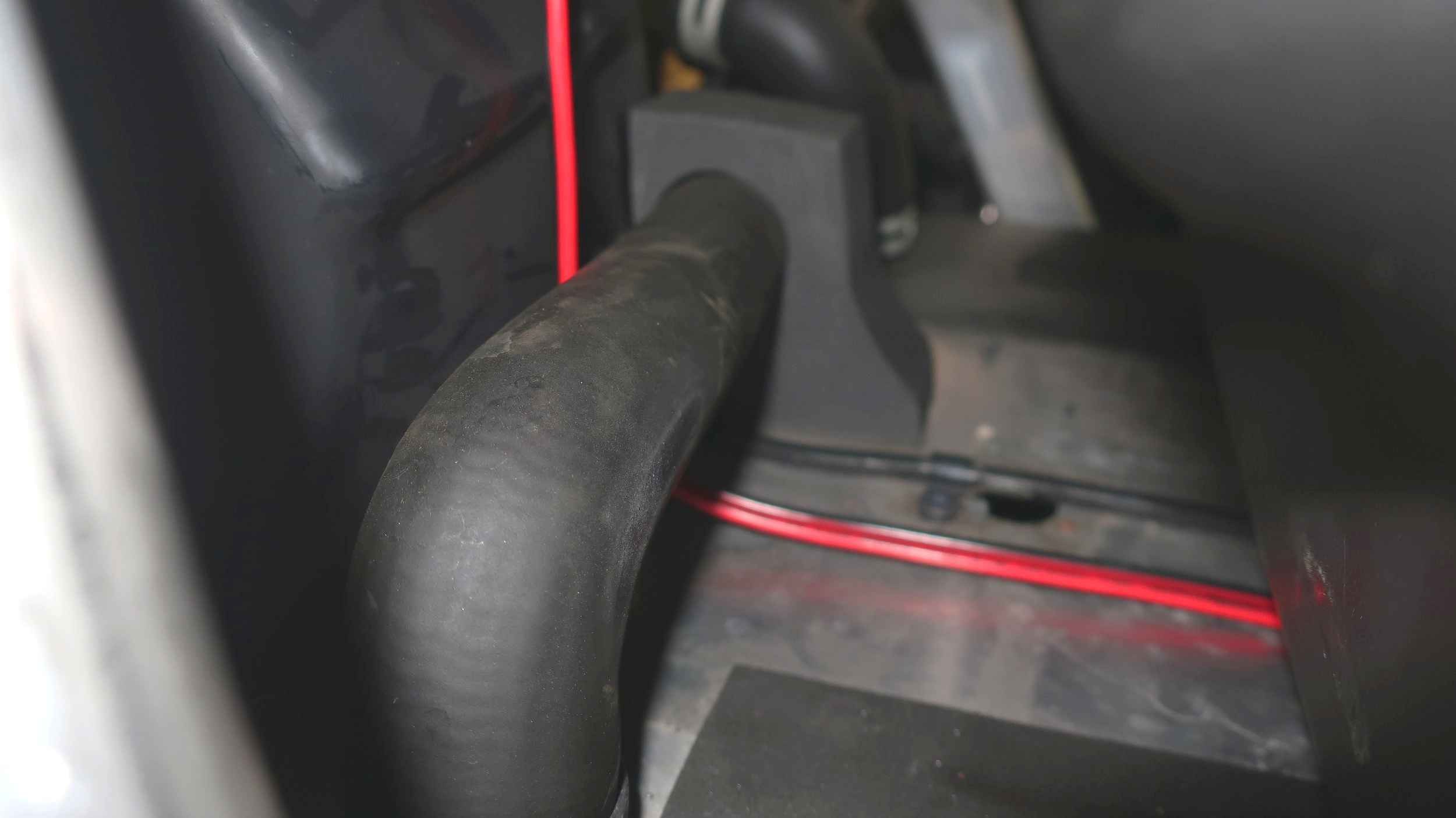
Locate the long ‘Under Tank Wire Provided’ and with the two prong end labeled ‘Toward Hood’ lift the clutch side of the tank and slide the wire under the tank from the clutch side until centered on the tunnel.
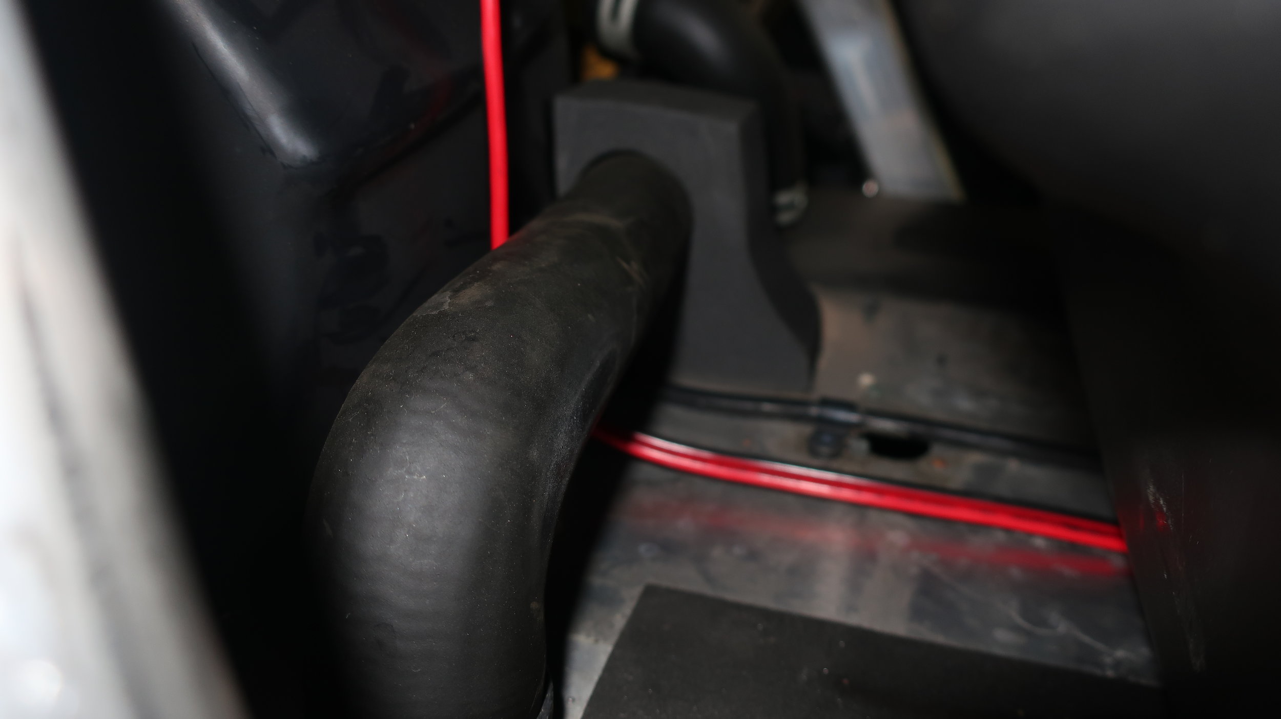
With the wire centered, run the 2 prong behind the coolant tube and behind the over structure brace towards the ECU. Leave excess wire in engine bay for now.
Step 7: Checking Wire Length Behind tank
With the wire under the tank, slide the tank back into place and ensure 8” of wire is exposed from behind the tank. Adjust slack accordingly to achieve 8”
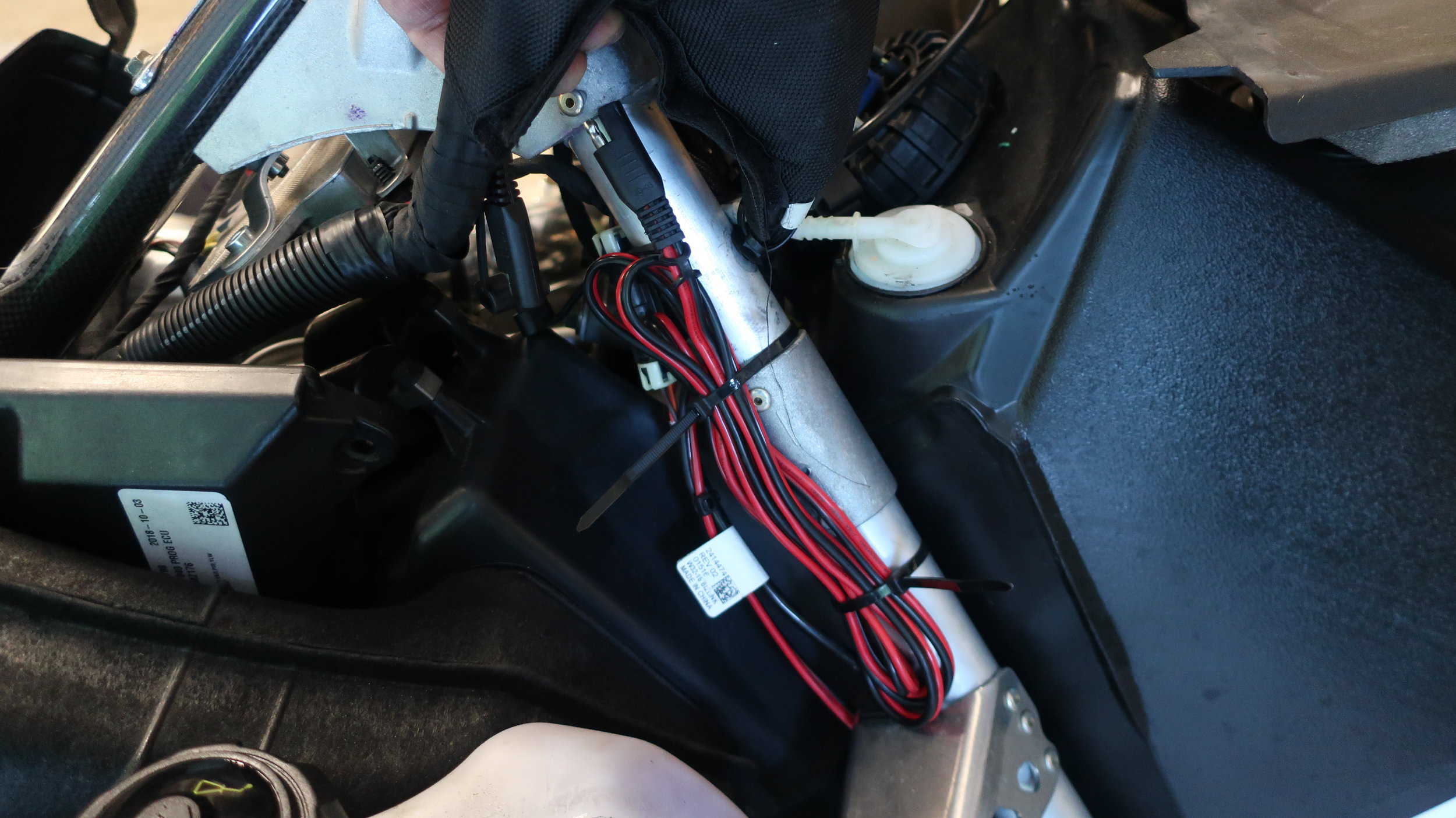
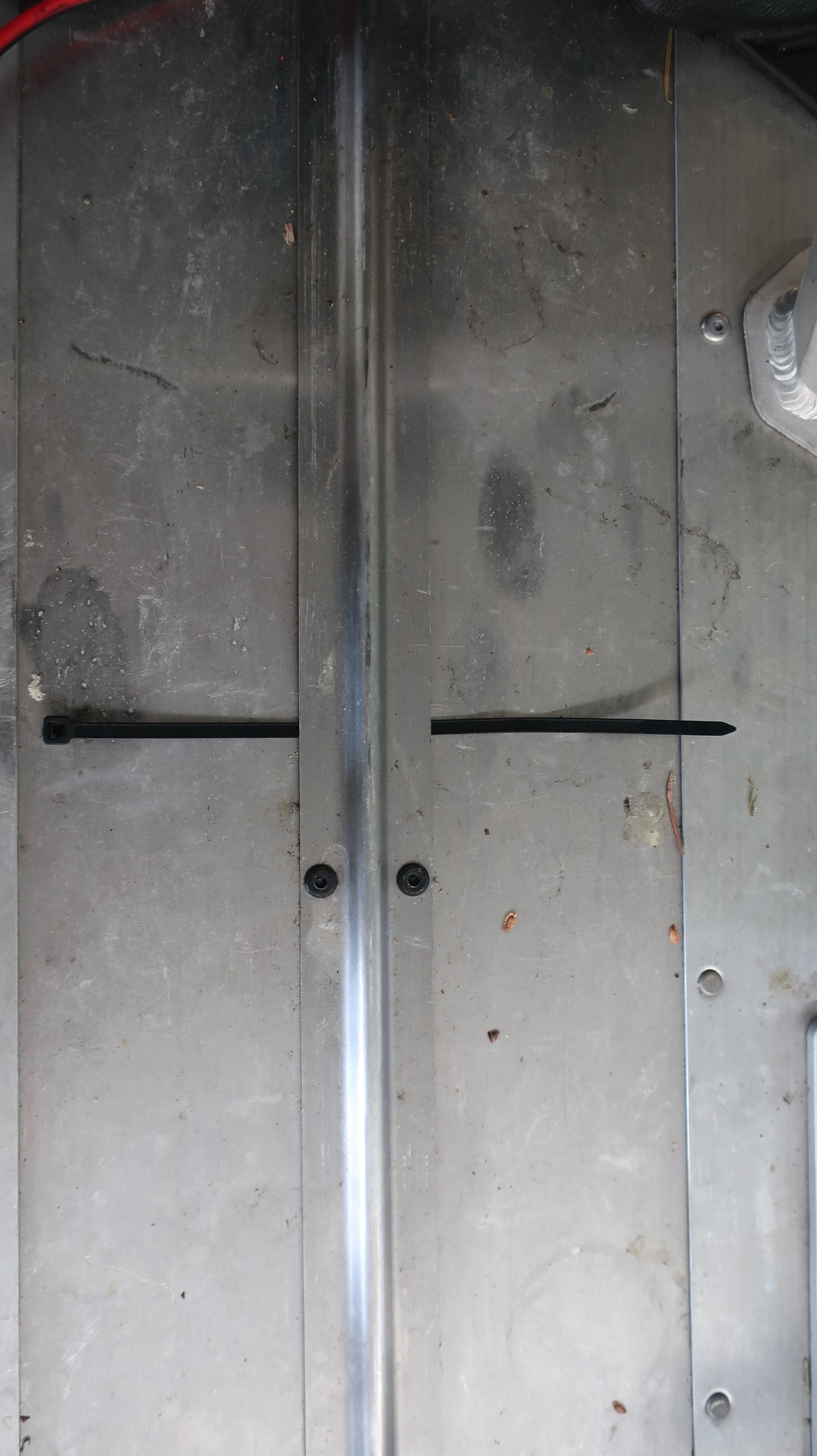
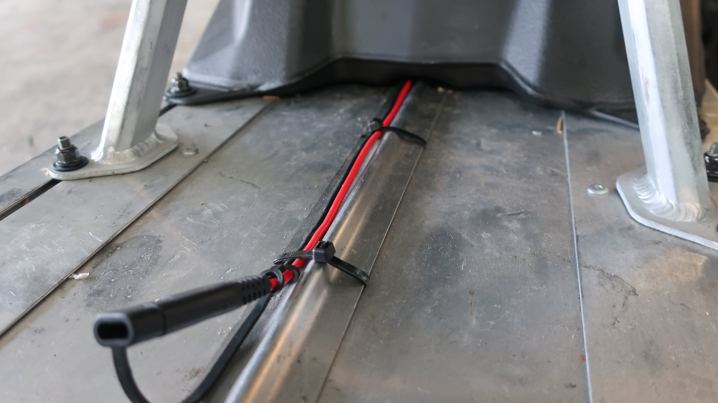
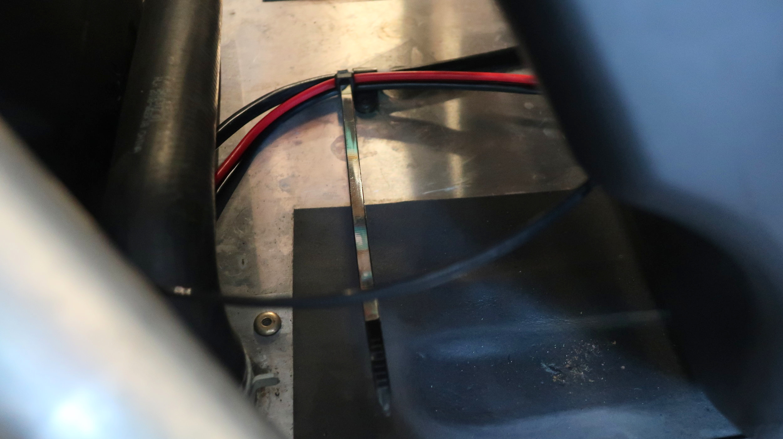
Once 8” has been set, run 2 zip ties under the tail light wire cover and secure the under tank wire to the tail light cover as shown in photos below.
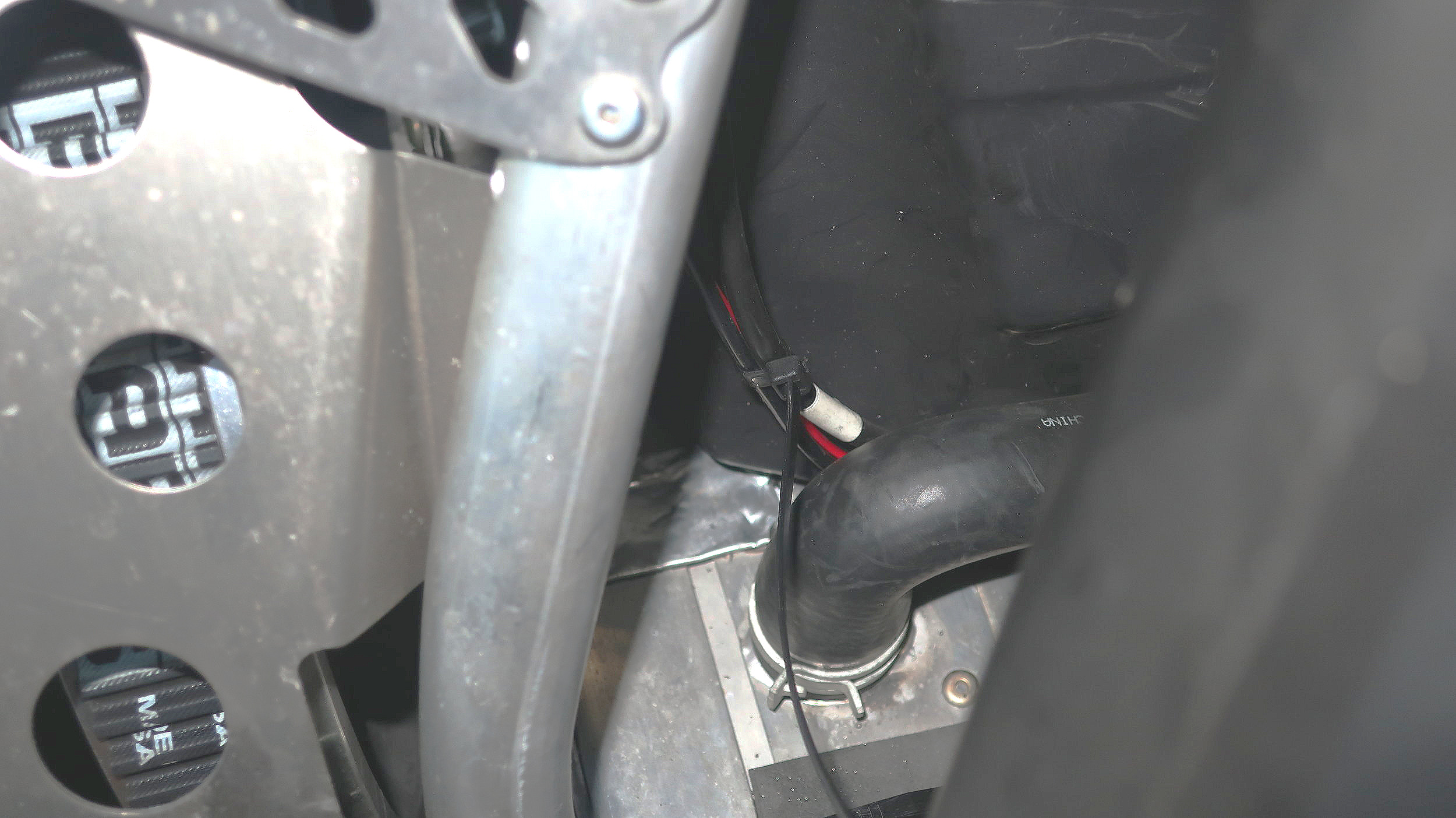
Slide tank backwards again and zip tie the tank wire to the tail light wire at the existing wire mount right in front of the coolant tube and above the coolant tube

Step 8: Secure the Tank and reinstall the seat
With all the wire secured under the tank you are ready to slide the gas tank forward and re-install the gas tank at the front and rear locations
After the tank is secured, reinstall the seat with respective fasteners
DO NOT OVER Torque Fasteners, Snug is Fine.
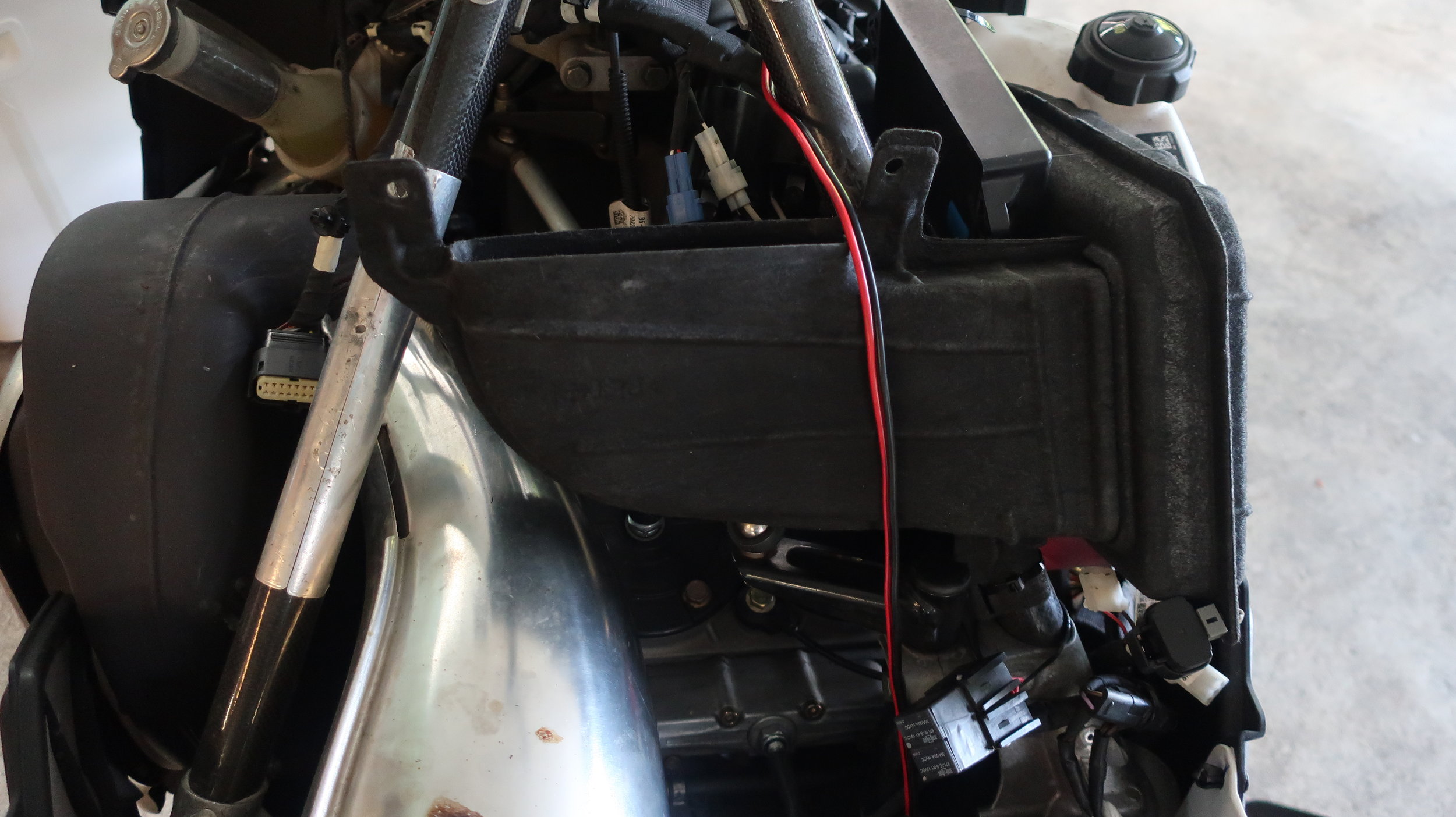
Step 9: Routing Wires Under the Hood
Run the wire over the airbox intake and leave excess hanging by exhaust pipe
Using 2 zip ties, secure the wire to the existing wiring harness

Step 10: Connect Power and securE excess Wire
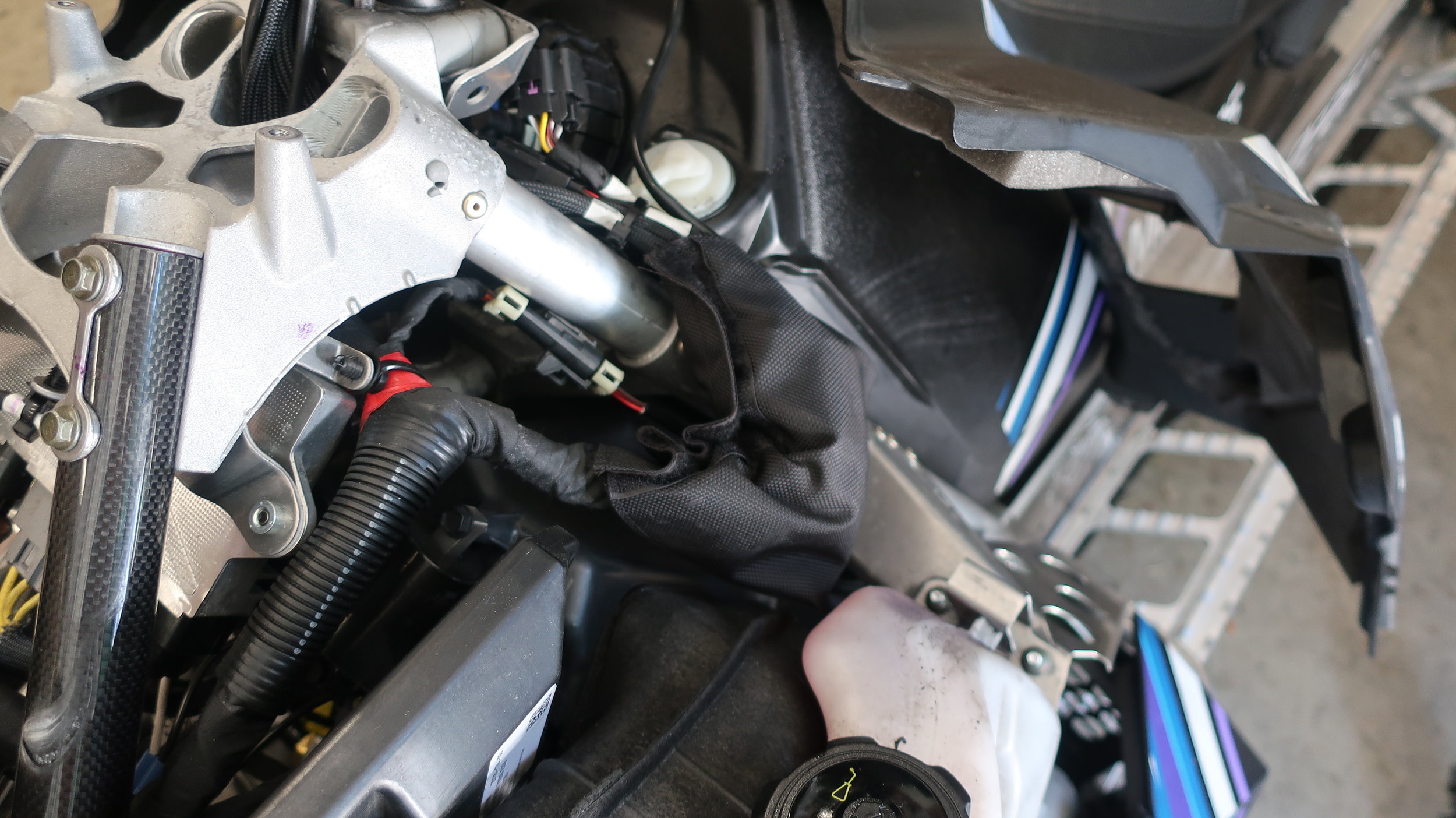
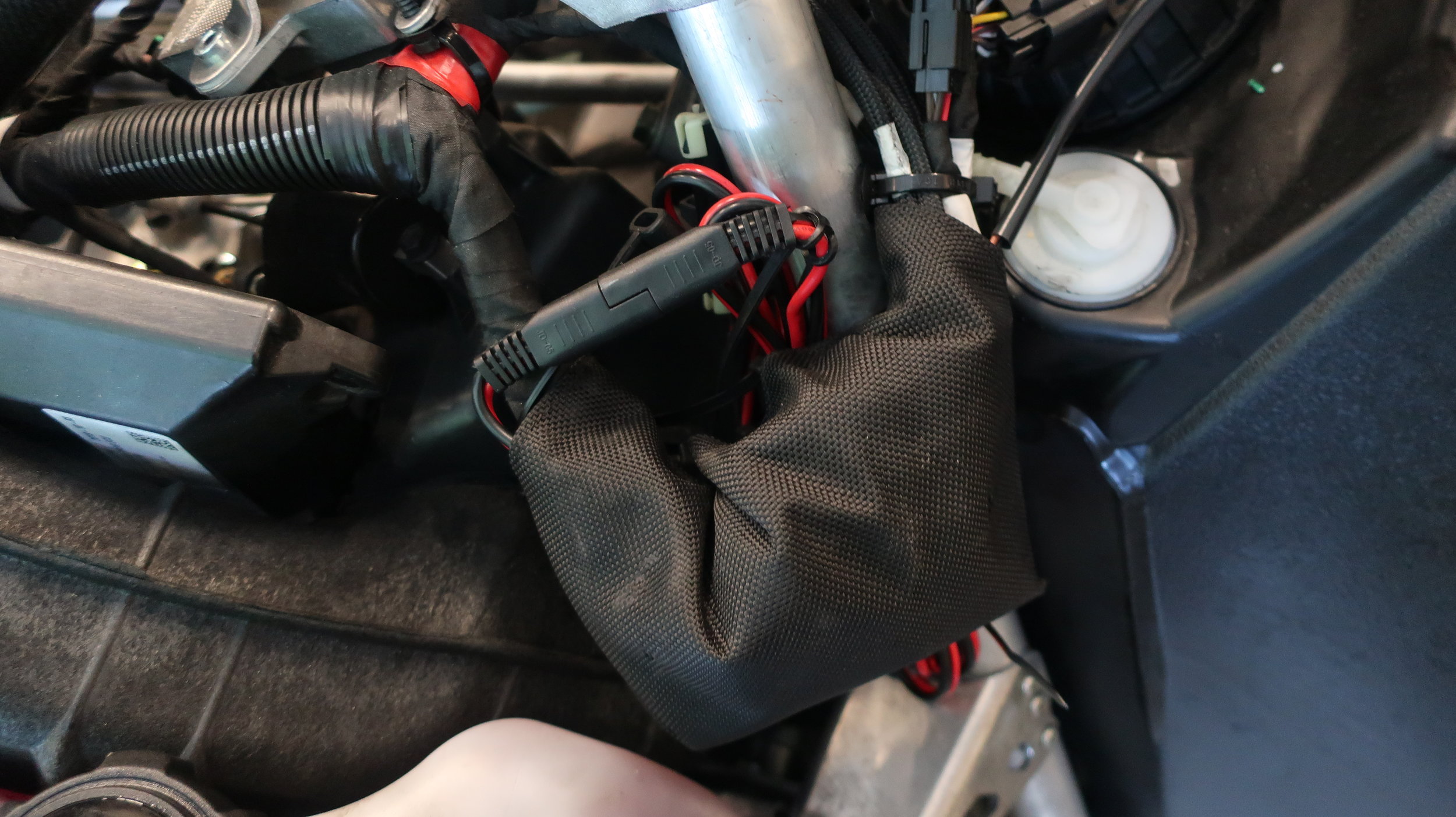
Locate the fabric bag on the clutch side of the snowmobile and open to expose wiring
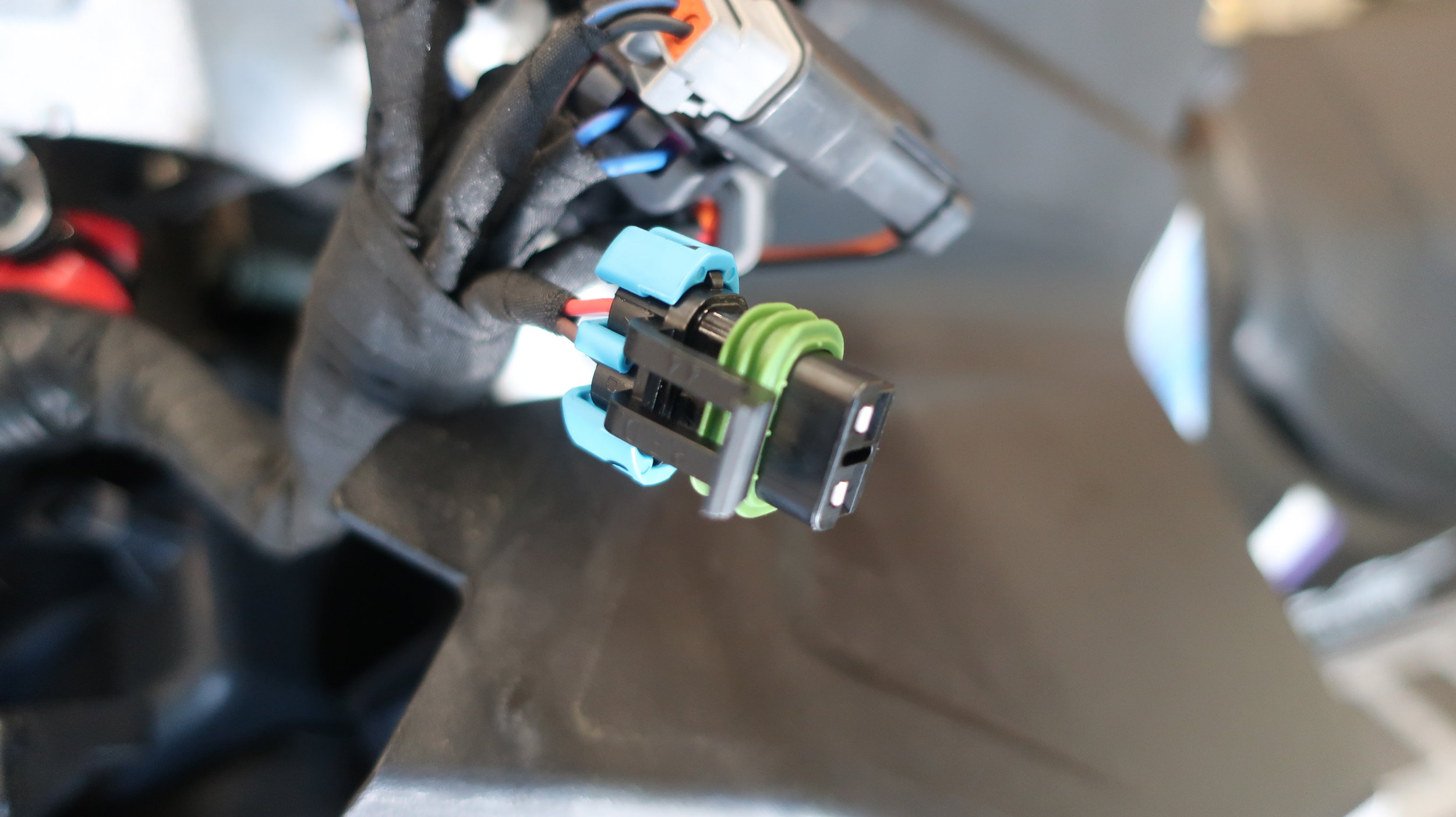
Identify electrical connector labeled ‘RCA ACCY Power’ and remove protective cap. If no protective cap is secured, then proceed to next step.
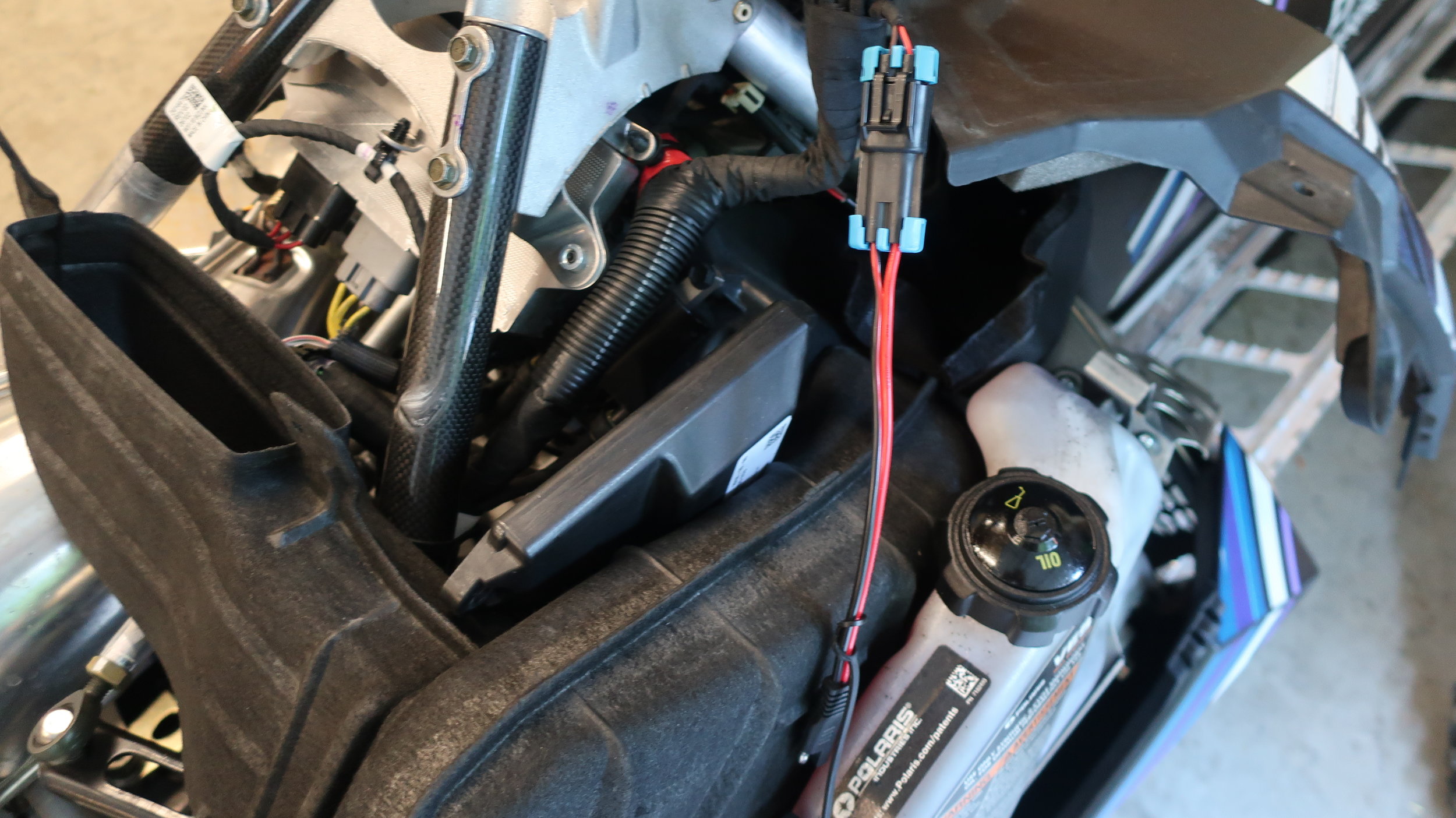
Connect supplied Machine Integration Wire, with the 2 prong wire pointing towards the front of the machine, then re-seal fabric bag.
Secure the excess wire to the over structure with supplied zip ties and connect 2 prong wires